
There's a decision sitting at the heart of every 800G network deployment that doesn't always get the attention it deserves. It's not about which transceiver speed to choose, or which vendor to go with. It's about physical architecture — specifically, whether to deploy OSFP-IHS or OSFP-RHS modules. Get it right and you've built a foundation that scales cleanly through the next wave of AI infrastructure. Get it wrong and you'll find out the hard way that the modules you ordered simply don't fit the equipment you're running.
This guide covers everything you need to make that call with confidence: what each architecture actually is, which equipment requires which form factor, how to plan your optical reach and breakout strategy, and how today's decision maps to tomorrow's 1.6T roadmap.
The 800G Inflection Point
The networking industry has seen technology transitions before, but the shift to 800G is happening faster than anything that preceded it. Industry analysts project 800G transceiver shipments will surge from 24 million units in 2025 to 63 million in 2026 — a 162% year-over-year increase driven almost entirely by AI infrastructure buildouts. For context, 400G took six or seven years to reach 20 million ports. 800G got there in three.
What makes this transition genuinely different is that you're not just selecting a faster transceiver. You're choosing between two fundamentally different physical architectures — OSFP-IHS (Integrated Heat Sink) and OSFP-RHS (Riding Heat Sink) — and that choice determines which host equipment you can use, how your racks are cooled, and whether your infrastructure can grow to 1.6T without replacing the hardware you're deploying today.
This isn't a detail to sort out later. It's the foundational decision that everything else builds on.
Understanding OSFP
OSFP stands for Octal Small Form-factor Pluggable — the "Octal" referring to its eight electrical lanes, each running at 100Gbps using PAM4 modulation to deliver 800Gbps aggregate. It's a hot-pluggable form factor developed by the OSFP MSA consortium, and it has become the dominant choice for 800G deployments for good reason.
Compared to QSFP-DD, OSFP's housing is about 22% larger. That extra space matters: it allows for a 30W power capacity versus 14W for QSFP-DD, better thermal headroom, and wider pin spacing that improves signal integrity. The trade-off is port density — more physical space per module means fewer ports per 1U switch. For AI networking where thermal management and signal integrity are the primary concerns, that trade-off is consistently worth making.
One thing worth understanding upfront: the eight-lane electrical and optical architecture is completely identical between IHS and RHS. The difference between these two form factors is purely thermal and mechanical. You're not choosing between different capabilities — you're choosing between different approaches to managing heat.
OSFP-IHS: Integrated Heat Sink
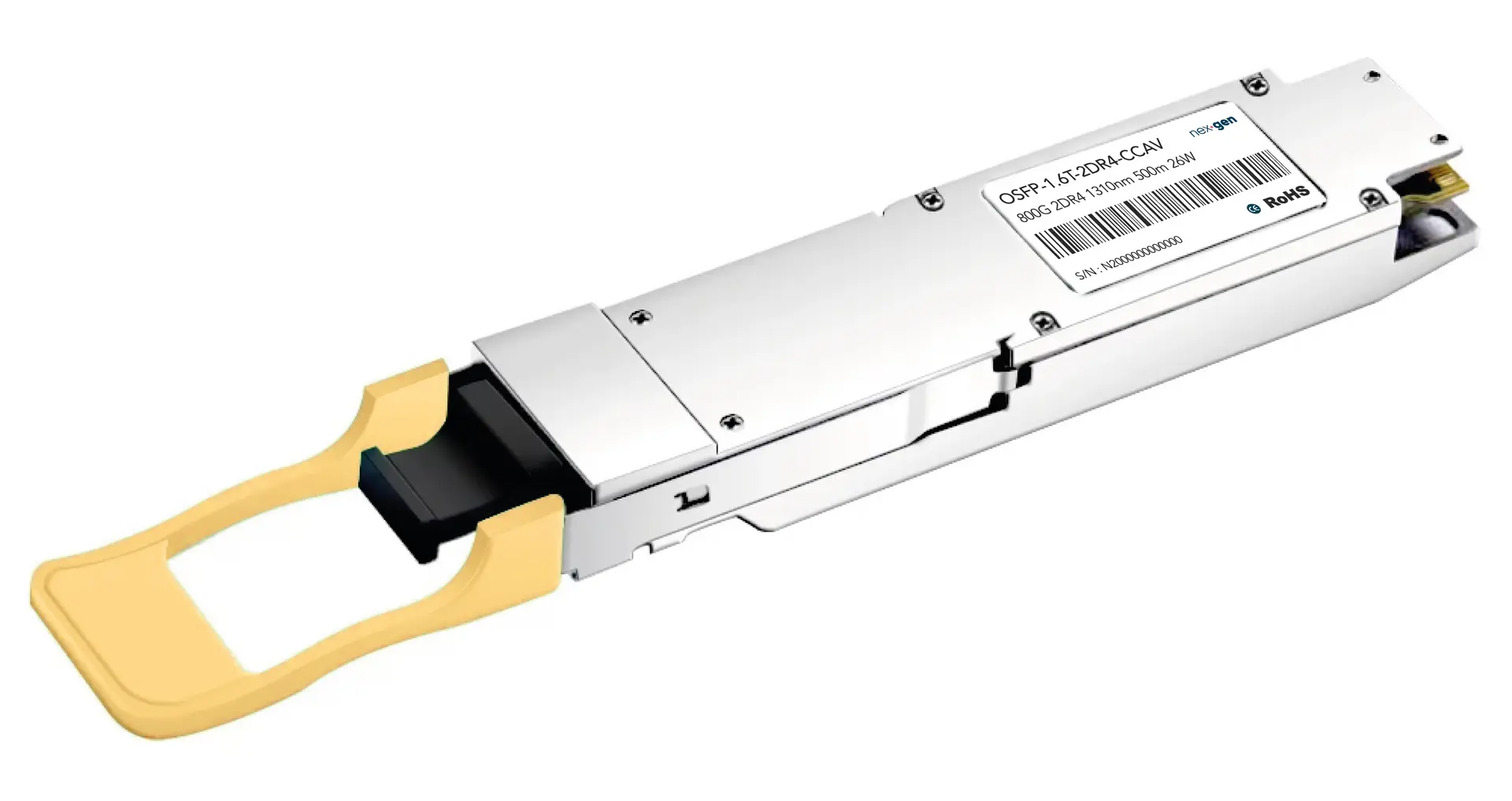
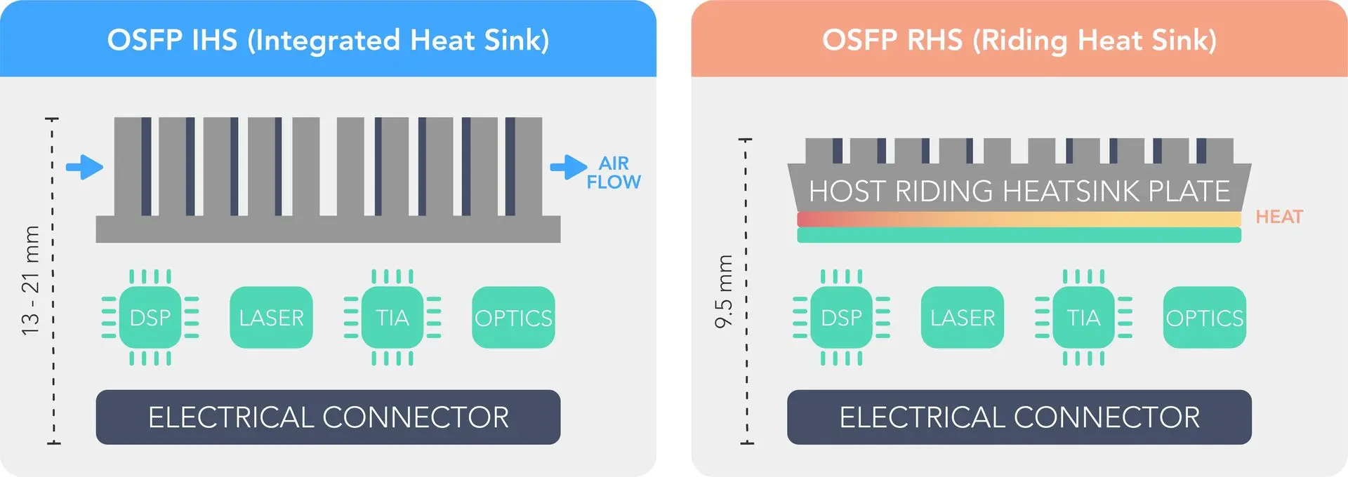
IHS modules have the heat sink built directly into the transceiver housing. Look at an IHS module and you'll see aluminum or copper fins rising from the top surface — that's the thermal solution, integrated at the factory. Total module height runs between 13mm and 21mm depending on fin design.
When airflow moves through the switch — typically front-to-back at 200 to 400 linear feet per minute — it interacts directly with those fins, drawing heat away from the module through convection. Heat generated by the DSP, laser driver, and optical components (typically 12 to 17W, up to 30W for coherent modules) moves through copper vias to the fins and out through the rear of the switch.
The appeal of IHS is its simplicity. The module manages its own thermal performance completely. No cold plates, no thermal interface materials, no alignment between module and host-side heatsink. You plug it in and the thermal solution is already there.
IHS modules come in open-top and closed-top variants. Open-top exposes the fins directly to airflow for maximum thermal performance but leaves them vulnerable to physical damage. Closed-top uses a smooth outer enclosure with internal fins — better mechanical protection with still-excellent thermal performance — and is the standard for production deployments.
OSFP-RHS: Riding Heat Sink
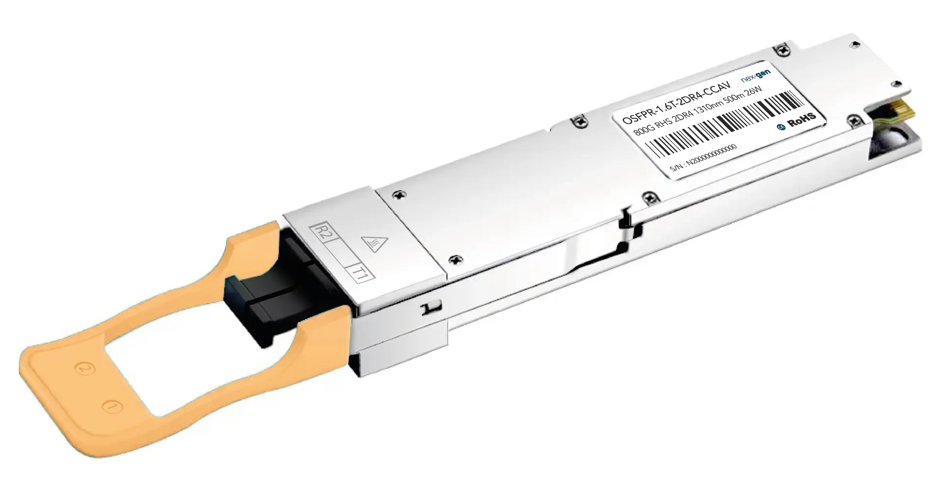
RHS takes the opposite approach. The module itself has no integrated heat sink — just a flat top surface at a standardized 9.5mm height, designed to mate with a thermal solution provided by the host system. That 9.5mm profile is roughly half the height of an IHS module, which is precisely what makes RHS viable in PCIe NICs, DPUs, and adapter cards where vertical space is tightly constrained.
In an RHS deployment, thermal management responsibility shifts from the module manufacturer to the host system designer. Heat generated inside the module travels to the flat top surface, then through a layer of thermal interface material (TIM) to whatever cooling solution the host provides — a riding heatsink for air-cooled environments, or a cold plate for liquid cooling.
That flat top surface is what makes RHS strategically interesting as liquid cooling adoption accelerates. Cold plates require flat, consistent contact surfaces, and RHS provides exactly that. In NIC and DPU deployments, the transceiver can share a unified thermal solution with the host silicon — one heatsink covering the entire card, which simplifies design and reduces component count.
One critical point: RHS modules require RHS-specific cages. The OSFP MSA defines different mechanical stops that physically prevent cross-insertion. An IHS module (13-21mm tall) won't fit in an RHS cage. An RHS module in a standard cage won't make proper thermal contact. This incompatibility is intentional — it eliminates a class of deployment failures before they happen.
Full Comparison
⚠️ IHS and RHS modules are NOT interchangeable as their cages are different !
The OSFP MSA intentionally prevented cross-insertion: as IHS modules are too tall (13 - 21mm) to fit in RHS cages and RHS modules lack thermal contact in standard cages
Quick Overview
|
Characteristic |
OSFP IHS |
OSFP RHS |
|
Module height |
13 - 21mm |
9.5mm |
|
Heat sink |
Integrated |
Host-provided |
|
Cooling method |
Air (front-to-back) |
Air or liquid |
|
Cage type |
Standard OSFP |
OSFP-RHS specific |
|
Primary use |
Switches |
NICs, DPUs, liquid-cooled |
|
Liquid cooling ready |
No |
Yes |
|
Max power (800G) |
33W |
33W |
|
Max power (1.6T) |
42.9W |
42.9W |
Everything below the heat sink — bandwidth, modulation, standards compliance, management interface — is identical between the two form factors.
Equipment Compatibility
Switches require IHS. Air-cooled spine and leaf switches use standard OSFP cages that are designed for finned-top modules. For example, Spectrum-4 SN5600 series switches with 51.2 Tbps capacity use 64 twin-port OSFP cages and exclusively accept IHS modules. The twin-port configuration is worth noting — each OSFP cage delivers two independent 400G ports, effectively doubling usable density.
The same applies to high-performance InfiniBand switches running XDR 800Gb/s. If you're populating a switch, start with IHS unless the datasheet explicitly states otherwise.
NICs and DPUs require RHS. PCIe card height constraints make IHS physically impossible in these environments. Single-port and dual-port OSFP NIC designs — whether targeting Ethernet or InfiniBand — are built around the 9.5mm RHS profile. There is no workaround here; the geometry simply doesn't work for IHS.
Quick References
|
Equipment |
Form Factor |
Notes |
|
Air-cooled spine/leaf switches |
IHS only |
Twin-port common |
|
InfiniBand switches |
IHS only |
Verify cage spec |
|
OSFP NICs |
RHS only |
PCIe height constraint |
|
DPUs (OSFP-based) |
RHS only |
Unified thermal design |
Module Types and Reach
Once you've determined IHS versus RHS, the next question is which optical variant you need. Reach requirements drive this decision.
|
Module |
Reach |
Fiber |
Connector |
Power |
|
SR8 |
50 - 100m |
MMF OM4 / OM5 |
Dual MPO-12 |
12 - 1 W |
|
DR8 |
500m |
SMF |
Dual MPO-12 |
14 - 17W |
|
2× FR4 |
2km |
SMF |
Dual LC |
13 - 14.5W |
|
2× LR4 |
10km |
SMF |
Dual LC |
15 - 18W |
|
ZR |
80km |
SMF coherent |
LC |
25 - 28W |
|
ZR+ |
120+ km |
SMF coherent |
LC |
27 - 30W |
The naming convention encodes reach: SR is short reach (multimode, under 100 m), DR is data center reach (500m single-mode), FR is fiber reach (2 km), LR is long reach (10km), ZR is coherent long-haul. The number indicates lanes — 8 means 8× 100G, 4 means 4× 100G per port.
Connector choice matters beyond just the physical interface. MPO-based modules (SR8, DR8) require structured cabling infrastructure with MPO trunk cables and cassettes. LC duplex modules (FR4, LR4, ZR) integrate with traditional patch panels and standard fiber management — a significant practical advantage if you're upgrading an existing facility.
Breakout Configurations
800G OSFP's breakout flexibility is one of its most useful practical features. A single 800G port can serve multiple lower-speed connections, which makes mixed-generation deployments much more manageable.
|
Source |
Breakout |
Cable |
Target |
|
800G DR8 |
2× 400G-DR4 |
MPO-16 to 2× MPO-12 |
Two 400G switches |
|
800G DR8 |
8× 100G-DR1 |
MPO-16 to 8× LC |
Eight 100G ports |
|
800G SR8 |
2× 400G-SR4 |
MPO-16 to 2× MPO-12 |
Two 400G SR4 ports |
|
800G SR8 |
8× 100G-SR1 |
MPO-16 to 8× LC |
Eight 100G ports |
Twin-port modules like 2×FR4 or 2×DR4 present two independent 400G ports through a single OSFP cage — each with its own MAC address, each connecting to a separate destination. This is distinct from cable-based breakout; the split happens inside the module.
A few things to get right when planning breakout deployments. MPO polarity (Type-A, Type-B, Type-C) needs to be consistent throughout your cabling infrastructure — mismatched polarity is a common cause of link failures that can take time to diagnose. MPO cables also have a larger minimum bend radius than LC duplex, so cable routing in tight spaces needs planning. And always validate breakout configurations in a lab environment before production rollout.
Linear Pluggable Optics (LPO)
LPO deserves serious attention in any 800G deployment planning, particularly for AI data centers with short-reach requirements.
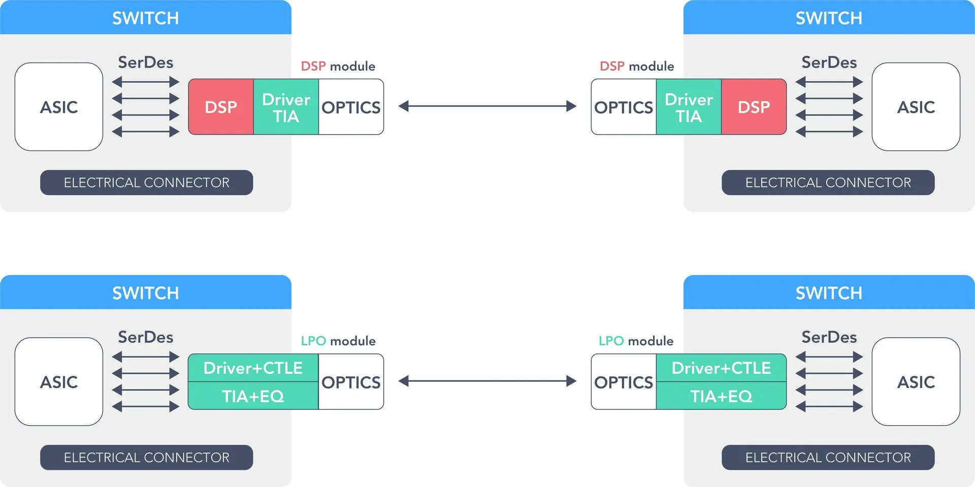
Traditional 800G modules include a DSP that handles signal retiming, equalization, FEC, and dispersion compensation. That DSP alone accounts for 6 to 8W — roughly half the module's total power budget. LPO eliminates the DSP entirely, shifting signal conditioning to the host switch's SerDes. The module retains only analog components: a TIA with continuous time linear equalization and linear drivers.
Quick Overview
|
Metric |
DSP Module |
LPO Module |
|
Power consumption |
14 - 17W |
7 - 8.5W |
|
Latency |
8 - 10ns |
< 3ns |
|
Component count |
Higher |
Lower |
The catch is that LPO requires host switch silicon with advanced SerDes capable of handling raw optical signals directly. Compatible platforms include Broadcom Tomahawk 5 and 6 and NVIDIA Spectrum-4. If your host equipment isn't on that list, DSP modules are the only option.
LPO also has reach limitations — without DSP-based dispersion compensation, it's practical only for reaches under 2km. For LR4, ZR, and ZR+ applications, DSP modules remain necessary.
For new AI data center builds with short-reach requirements and compatible switch silicon, LPO should be the default specification. The power and latency benefits compound significantly across thousands of ports.
A middle-ground option worth knowing about: Linear Receive Optics (LRO) uses DSP on transmit and linear on receive, delivering roughly 25% power savings with better interoperability for moderate-reach scenarios.
Decision Framework
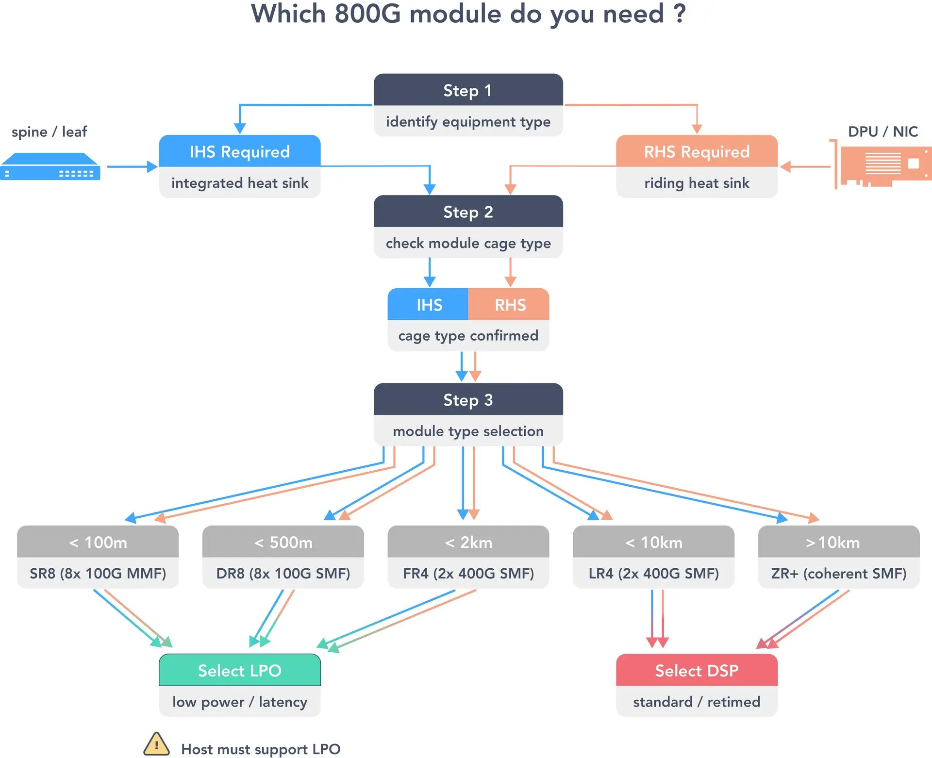
Work through these steps for every equipment platform in your deployment.
Start by identifying the equipment category. Switches almost universally require IHS. NICs, DPUs, and adapter cards almost universally require RHS. Start here and you've narrowed the decision significantly.
Then verify the cage specification. Don't assume — check the datasheet. "OSFP cage" or "Standard OSFP" means IHS compatible. "OSFP-RHS cage" or "flat-top OSFP" means RHS required. If it's ambiguous, a five-minute call to the equipment vendor is worth it to avoid a five-week procurement delay.
Next, map reach requirements to module types:
|
Connection |
Distance |
Module |
|
Same rack |
< 3m |
DAC |
|
Cross-rack |
3 - 10m |
AEC |
|
ToR to leaf |
10 - 100m |
SR8 or AOC |
|
Leaf to spine |
100 - 500m |
DR8 |
|
Building to building |
0.5 - 2km |
FR4 |
|
Campus backbone |
2 - 10km |
LR4 |
|
Metro DCI |
10 - 80km |
ZR coherent |
Then evaluate LPO. For reaches under 2km with compatible host silicon, specify LPO and plan for 7 to 8.5W per port instead of 14 to 17W. For everything else, standard DSP modules.
Finally, consider the 1.6T upgrade path. Both IHS and RHS form factors are compatible with OSFP1600 modules, meaning your cage infrastructure remains valid through the next generation. Plan for this now rather than discovering a compatibility gap at upgrade time.
Implementation Best Practices
A few things that separate smooth deployments from painful ones.
Before procurement, confirm cage types in all target equipment, validate airflow capacity for IHS deployments or cold plate specs for RHS, verify fiber type matches module requirements, and check SerDes compatibility if specifying LPO modules.
Order exact part numbers that specify the form factor explicitly — IHS or RHS should appear in the part number or documentation. Build in 10 to 15% spare inventory for failure replacement. And plan procurement timelines carefully — lead times of 12 to 24 weeks are not unusual for 800G modules.
The most common deployment mistakes worth explicitly avoiding: ordering IHS modules for NIC deployments (they physically won't fit), underestimating transceiver thermal contribution (32 ports at 16W each adds 512W to your rack budget — roughly equal to the switch silicon itself), mixing fiber types (DR8 requires single-mode fiber; connecting to multimode infrastructure will not work), and skipping interoperability testing before production rollout.
The Road to 1.6T
1.6T is already shipping in early production volumes, with mainstream availability expanding through 2026 and broad adoption expected by 2027. The transition follows a clear path:
|
Timeframe |
Milestone |
|
2025 |
Initial production, hyperscale deployments |
|
2026 |
Volume production, broader availability |
|
2027 |
Mainstream adoption |
Two form factors matter for 1.6T planning. OSFP1600 is backward compatible with current OSFP cages — both IHS and RHS variants exist, and both work with today's cage infrastructure. OSFP-XD uses a new cage design with 16 lanes for higher density, but requires new hardware and is not backward compatible.
The silicon roadmap is equally important: Broadcom Tomahawk 6 at 102.4 Tbps is shipping now, Spectrum-6 is expected in 2026, and Tomahawk 7 at 204.8 Tbps is on the 2027 horizon.
The practical implication for decisions made today: if you deploy standard OSFP cages (IHS) in your switches and OSFP-RHS cages in your NICs, your infrastructure is directly upgradeable to 1.6T by swapping in OSFP1600 modules — no cage replacement required. The hardware investment made now carries through to 2027 and beyond before OSFP-XD's density advantages justify a fresh hardware cycle.
Pulling it all together
The IHS versus RHS decision isn't a quality judgment — both are well-engineered solutions optimized for different contexts. IHS is the right answer for air-cooled switches. RHS is the right answer for NICs, DPUs, and liquid-cooled infrastructure. LPO is the right default for short-reach deployments with compatible host silicon. And both form factors scale cleanly to 1.6T without requiring a cage refresh.
Nexgen's engineering team works through these decisions with network architects every day — mapping form factor, cooling strategy, reach requirements, and upgrade timelines into a deployment plan that holds up across multiple hardware generations. If you're planning an 800G rollout and want to pressure-test your specifications, we're happy to work through it with you.