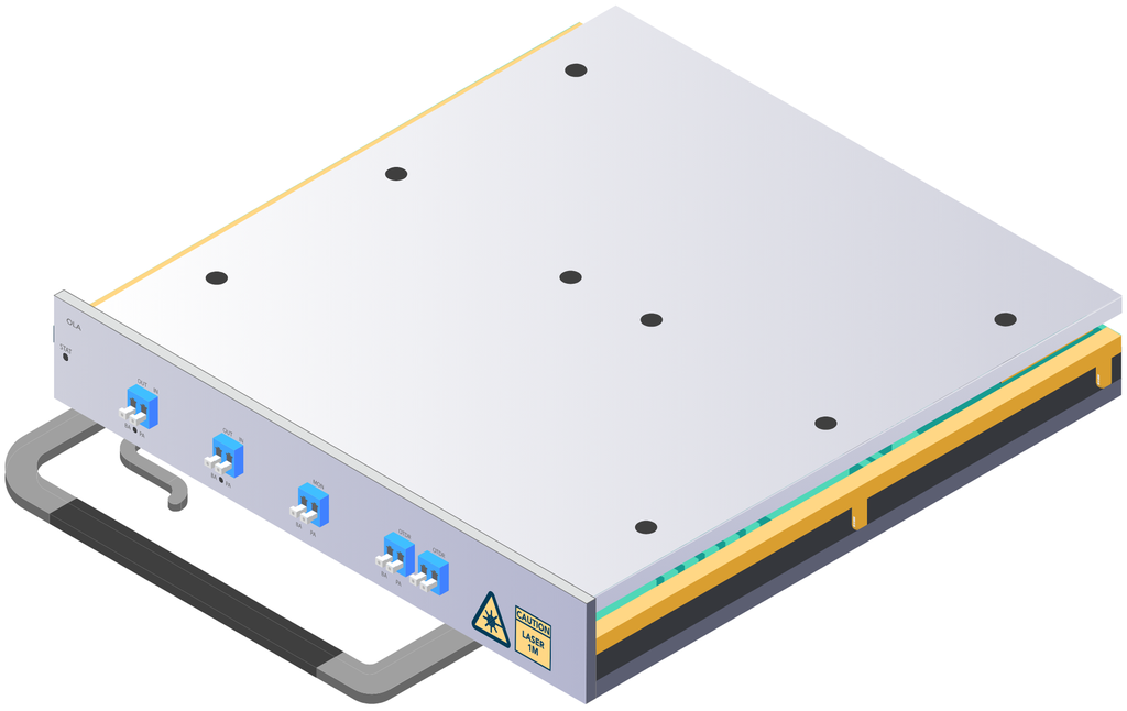


Optical Line Amplifier Card for DCI Chassis
The Optical Line Amplifier Card for DCI Chassis is a variable-gain bidirectional line amplifier for mid-span optical relay stations (OLA): it periodically compensates fibre-span loss to extend transmission distance. Two independent line-amplifier stages (LA1, LA2) each carry one direction of a bidirectional line pair. Available in six gain/band configurations covering the extended C-band or the ultra-wide C-band, with matched (LA1=LA2) or mixed gain pairing, gain set to AGC or APC mode and adjusted continuously within range.
Highlights
Six gain/band configurations
OLA-25/OLA-35A/OLA-35B cover the extended C-band (1528–1568nm); OLA-25U/OLA-35AU/OLA-35BU cover the ultra-wide C-band (1524–1572.3nm) with higher output power on 25-type stages and different noise/slope figures.
Matched or mixed gain pairing
OLA-25 and OLA-35A/OLA-35AU pair two identical-gain stages (15–25dB or 22–35dB); OLA-35B/OLA-35BU mix one of each (LA1 15–25dB, LA2 22–35dB) for asymmetric spans.
Continuously adjustable gain
LA1 and LA2 each set to AGC (automatic gain control) or APC (automatic power control) mode, with gain adjustable throughout the stated range rather than fixed steps.
Bidirectional mid-span relay
A fixed LA1 + LA2 pair amplifies both directions of a line span independently, extending reach between terminal or other relay stations.
Built-in OSC, MON and OTDR
Standard optical supervisory channel, 2 MON taps (21–23dB split) and 4 OTDR monitoring ports (1625nm) - one on each side of each LA stage - for DCN communication and fibre diagnostics.
Automatic power reduction
Supports APR (automatic power reduction) for laser safety on fibre break, on all six configurations.
Functional Structure
Format
Specifications
| Specification | All models | |||||
|---|---|---|---|---|---|---|
| Working Mode | AGC or APC, settable (LA1 and LA2) | |||||
| Gain Flatness | <1.5dB | |||||
| Polarization Dependent Loss | <0.5dB | |||||
| Gain Stability | ±0.5dB | |||||
| Reflection Coefficient | <-30dB | |||||
| MON Port | Standard, 0.5% splitting ratio (21–23dB), LA1 and LA2 | |||||
| OTDR Monitoring Channel | 1625nm, <1dB channel loss, 4 ports (LA1-IN, LA1-OUT, LA2-IN, LA2-OUT) | |||||
| VOA | Input front on both LA1 and LA2, <1dB insertion loss, 0–15dB adjustment range | |||||
| OSC Wavelength | 1510nm | |||||
| Safety | Automatic power reduction (APR) on fibre break | |||||
| Slots Occupied | 2 (compatible with the OTN DCI platform range) | |||||
| Specification | 25 | 35A | 35B | 25U | 35AU | 35BU | ||||||||||||||||||||||||||||||||||||||||||||||||||||||||||||||||
|---|---|---|---|---|---|---|---|---|---|---|---|---|---|---|---|---|---|---|---|---|---|---|---|---|---|---|---|---|---|---|---|---|---|---|---|---|---|---|---|---|---|---|---|---|---|---|---|---|---|---|---|---|---|---|---|---|---|---|---|---|---|---|---|---|---|---|---|---|---|---|
| Band | Extended C | Extended C | Extended C | Ultra-wide C | Ultra-wide C | Ultra-wide C | ||||||||||||||||||||||||||||||||||||||||||||||||||||||||||||||||
| Wavelength Range | 1528–1568nm | 1528–1568nm | 1528–1568nm | 1524–1572.3nm | 1524–1572.3nm | 1524–1572.3nm | ||||||||||||||||||||||||||||||||||||||||||||||||||||||||||||||||
| Max. Total Output Power | ≥21dBm | ≥21dBm | ≥21dBm | ≥23dBm | ≥21dBm | LA1 ≥23dBm LA2 ≥21dBm | ||||||||||||||||||||||||||||||||||||||||||||||||||||||||||||||||
| Gain Slope | -3 to 0dB | -3 to 0dB | -3 to 0dB | -5 to 1dB | -5 to 1dB | -5 to 1dB | ||||||||||||||||||||||||||||||||||||||||||||||||||||||||||||||||
| Output Power Detection Range | -2 to 22dBm | -2 to 22dBm | -2 to 22dBm | -5 to 23.5dBm | -5 to 23.5dBm | -5 to 23.5dBm | ||||||||||||||||||||||||||||||||||||||||||||||||||||||||||||||||
| LA1 | ||||||||||||||||||||||||||||||||||||||||||||||||||||||||||||||||||||||
| Gain Range | 15–25dB | 22–35dB | 15–25dB | 15–25dB | 22–35dB | 15–25dB | ||||||||||||||||||||||||||||||||||||||||||||||||||||||||||||||||
| Noise Figure |
|
|
|
|
|
| ||||||||||||||||||||||||||||||||||||||||||||||||||||||||||||||||
| Input Power Detection Range | -28 to 6dBm | -35 to 0dBm | -28 to 6dBm | -26 to 8dBm | -33 to 1dBm | -26 to 8dBm | ||||||||||||||||||||||||||||||||||||||||||||||||||||||||||||||||
| OSC Operating Rate | 1.25Gb/s | 155Mb/s | 1.25Gb/s | 1.25Gb/s | 155Mb/s | 1.25Gb/s | ||||||||||||||||||||||||||||||||||||||||||||||||||||||||||||||||
| LA2 | ||||||||||||||||||||||||||||||||||||||||||||||||||||||||||||||||||||||
| Gain Range | 15–25dB | 22–35dB | 22–35dB | 15–25dB | 22–35dB | 22–35dB | ||||||||||||||||||||||||||||||||||||||||||||||||||||||||||||||||
| Noise Figure |
|
|
|
|
|
| ||||||||||||||||||||||||||||||||||||||||||||||||||||||||||||||||
| Input Power Detection Range | -28 to 6dBm | -35 to 0dBm | -35 to 0dBm | -26 to 8dBm | -33 to 1dBm | -33 to 1dBm | ||||||||||||||||||||||||||||||||||||||||||||||||||||||||||||||||
| OSC Operating Rate | 1.25Gb/s | 155Mb/s | 155Mb/s | 1.25Gb/s | 155Mb/s | 155Mb/s | ||||||||||||||||||||||||||||||||||||||||||||||||||||||||||||||||
Ordering Information
| Name | Optical Line Amplifier Card for DCI Chassis |
| Description | OLA variable-gain bidirectional line amplifier card, 2 slots. Two independent line-amplifier stages (LA1, LA2), each 15-25dB or 22-35dB adjustable (matched or mixed pairing), AGC/APC settable, for mid-span optical relay (OLA) stations; available in extended C-band (1528-1568nm) or ultra-wide C-band (1524-1572.3nm, higher output power on 25-type stages); standard OSC, MON and OTDR monitoring, VOA on both stages, APR safety. |
| Part Number | DCI-OLA-{Model}-2S |
| {Model} | 25 · 35A · 35B · 25U · 35AU · 35BU, required - number/letter sets the LA1/LA2 gain pairing (25 = both 15–25dB, 35A = both 22–35dB, 35B = mixed 15–25dB/22–35dB); optional U suffix selects the ultra-wide C-band version (higher output power on 25-type stages, different noise/slope) |